state machine semantics, types, interfaces, components, interaction diagrams and metamodels. The UML 1.1 standard was accepted on November 17th, 1997. The current UML version is UML 1.4. Besides, OMG developed the XML (eXtensible Markup Language) standard for UML model presentation, XMI (XML Metadata Interchange).
2.1. Architecture and UML metamodels | top ^ |
A noticeable fact is that a UML structure can be described itself using UML. The primary element of the UML architecture is the concept of metamodel (a model of a higher level). Thus, we can consider some specific system of objects as a zero-level model of itself. A model describing classes, associations and behavior of these objects is a first-level model (or simply model). Usually, its structure is more simple than the structure of the original system. The model describing classes of elements of different first-level models (classes, associations, attributes, operations, states etc.) is a second-level model or metamodel. Moreover, the UML architecture defines the existence of a metametamodel or the third-level model describing the structure of different metamodels. Its structure is very simple, and cannot be simplified (i.e., if we would try to reduce it to a fourth-level model, a metametametamodel, the latter will have the same structure as the original third-level model or the metametamodel). The model of all levels are described by UML terms in the language specification.
The UML (Unified Modeling Language) is a graphical language used for visualization, specification, designing and documenting systems. UML is most widely applied for modeling business processes and software systems for automation of these processes. Using UML, one can develop a detailed plan of the system to be created, which will reflect both the conceptual elements and the implementation particularities. UML recently became the industrial standard in the area of software systems design and enterprise business modeling.
Classes and relationships between classes are the typical objects of a static UML model. Classes are the primary building blocks of any object-oriented system. They represent the description of a collection of objects with common attributes, operations, relationships and semantics. A class implements one or several interfaces.
Classes are used to compile the dictionary of the system under development. It can include either abstractions (which are parts of the respective subject area) or classes providing the base for implementation. The software, hardware and conceptual entities are described by classes. Well-structured classes are distinguished by distinct boundaries, they are helpful in setting a properly balanced distribution of responsibilities within the system.
The entities modeled by classes can have no counterparts on the software side. For instance, for a trade company the employees that send delivery notes or the salespersons are as well the parts of the business process to be automated, and so on.
Classes are rarely independent. Usually they interact in some way one with another. Thus, when you model the system, you need not only to identify the entities, but also to describe the relationships between these entities. There are three basic type of relationships:
- Dependencies describing the inter-class utilization relationships;
- Generalizations linking the generalized classes with specialized ones;
- Associations which represent the structural relationships between objects (an aggregation is a particular case of a generalization);
Each of these types allows to combine abstractions in different ways.
An important feature of UML is its scalability. UML was designed as a modeling language applicable in the most different areas. Since it was impossible to cover all possible areas of UML applicability at the design stage, the features providing scalability were incorporated in the language. The primary one is the use of stereotypes. A stereotype is a label adding a specific sense to a UML element. Thus, e.g., the UML class labeled with a "boundary" stereotype designates an interface class (i.e. a class of objects providing the system interface with the outer world). For each specific application of UML an appropriate set of stereotypes can be defined.
The most important part of a static (structural) UML model are the class diagrams. The static model also includes object diagrams, component diagrams and deployment diagrams. The dynamic (behavioral) model includes state diagrams, activity diagrams, use-case diagrams (diagrams describing different scenarios or precedents of system use), sequence diagrams and cooperation diagrams.
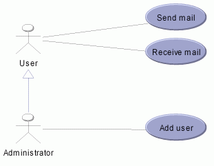
Usually the modeling of a system or process starts from use-case diagrams. These diagrams are used to separate external (in respect to the system or process) entities and the functionality provided to these entities by the system.

Fig. 1. Use-case diagram. Thus, the diagram above displays that the system has two kinds of users: User (regular user) and Administrator. The system provides the User with the ability to send and receive mail, and the Administrator (inherited from User) with an extra function of adding a regular user.
Use-case diagrams represent the appearance of the system, describing its upper-level interface. The internal mechanics of the system are usually depicted by other types of diagrams. The ones most frequently used are object diagrams and class diagrams.
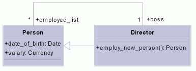
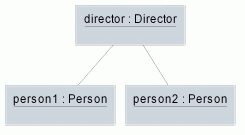
  Fig. 2. Class diagram, object diagram. In the example above, the class diagram contains two classes, Person and Director, linked by the inheritance relationship (arrow) and by the association (line). The object diagram on the right describes a particular case of link between individual objects. The difference between class and object diagrams is obvious - the first ones describe all possible links between the classes and completely determine the set of states of the system of objects; the second ones represent the system of objects at some particular time moment, providing a picture of a particular case of system configuration.
Class and object diagrams describe the static structure of a system (possible links and associations between objects and classes), while sequence and collaboration diagrams represent the dynamics of interaction between objects. These diagrams are used to represent possible scenarios of interaction between objects, sequences of message exchange, control and data flows.
 Fig. 3. Sequence diagram, interaction diagram. Both diagrams on Fig.3 represent the same process - a user sends a message. As you can see, the user sends a "send message" message to the "system core" object which (in course of handling this message) sends a "send message" to the "mail server" object. "Mail server" returns the object "result" which is then passed to the user. Sequence and collaboration diagrams provide a different presentation of the same things, the diagrams of one type can be automatically converted to the other one. These diagrams are similar to object diagrams since both represent a particular case of implementing the interaction between system objects.
Other types of diagrams (state and activity diagrams) are used to completely define the dynamics of interaction between the objects.
 Fig. 4. State diagram On the picture above you can see the state diagram for a common phone. State diagrams are used to describe states of objects and systems of objects along with the procedures of transitions between different states. Transitions are displayed as arrows labeled with respective initiating messages.
 Fig. 5. Diagram of activities The activity diagram above displays the process of initiating a project in some company. The diagrams of this type represent activities (the difference with states is that one cannot remain within an activity after finishing the described actions) and the sequence of transitions between the activities. Parallel activities (control flow forks) are represented by the so-called fork-join states (displayed as solid vertical or horizontal bars).
Logical components of a software system are represented by component diagrams. Components can correspond to both static (packages, libraries, executable modules) and dynamic (flows, processes, programs) system elements, as well as to physical elements/units (server, computer, mobile phone etc.). Components inherit all common properties of regular UML classes, i.e. they can have attributes, operations, interfaces and can be linked by associations.
 Fig. 6. Components diagram. The diagram above represents the components of a mail system (the functions of this system were described by the use-case diagram in Fig. 1).
 Fig. 7. Deployment diagram. Deployment diagrams represent possible system configurations - specifically, the possible distribution of components between physical units (nodes) of the system.
|


